

Graph View
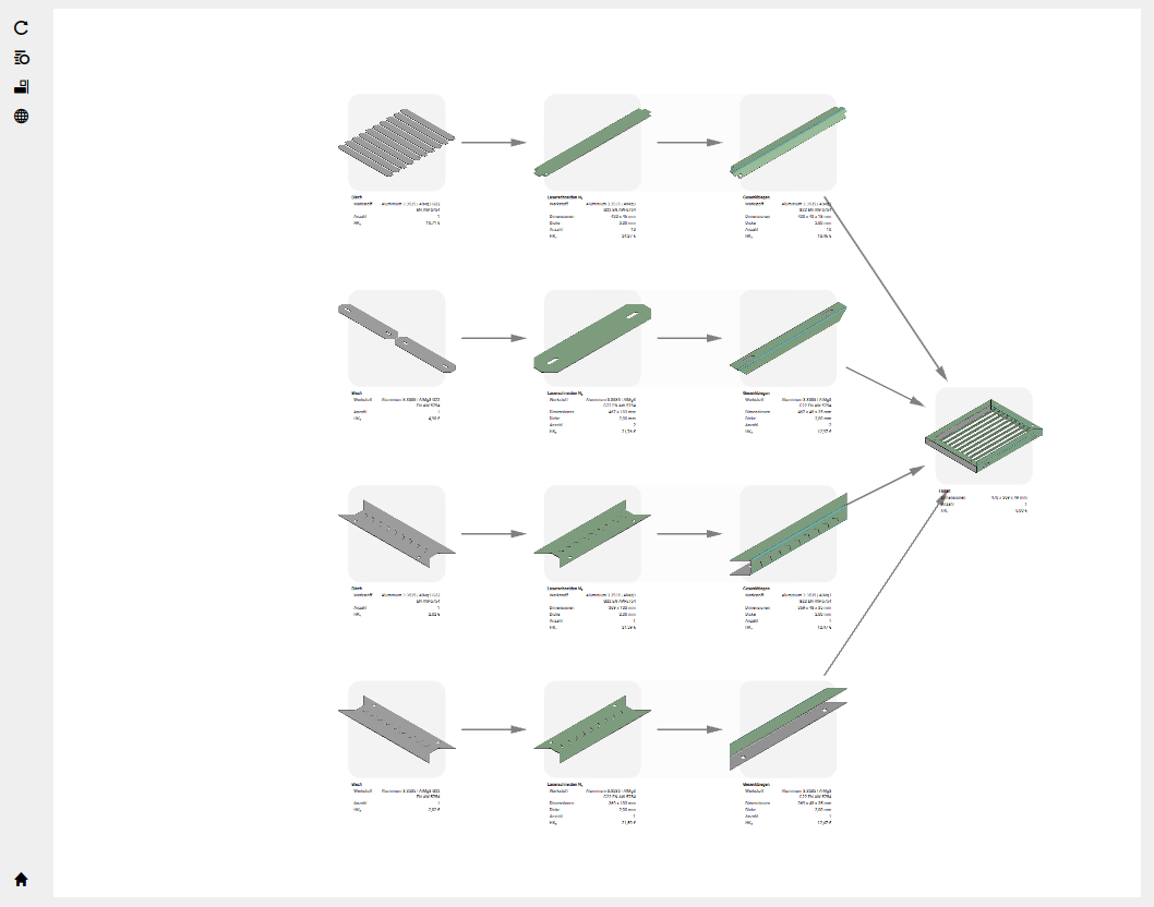
The Graph View displays your part as a node-and-edge diagram — each node represents a manufacturing step (cutting, bending, coating, and so on), and the edges show how material flows between them. Use it to see the full process at a glance, reposition nodes, and select items for inspection in other panels.
Nodes
Each node is a rounded rectangle showing:
- A thumbnail of the part or geometry at that step
- Where applicable, a background colour and, on hover, a message above the node — yellow for warnings, orange for recoverable errors, red for errors, and grey for additional information
- Text that appears on hover — the step name and key details
Click a node to select it. Hold Ctrl and click to add multiple nodes to the selection. Double-click a node to select all nodes of the same type.
Edges
Edges are grey lines with arrow heads that show the direction of material flow from one step to the next.
Toolbar
The toolbar on the left of the Graph View has the following buttons:
| Button | Action |
|---|---|
| Add Purchased Part | Adds an external/purchased part to the graph — a part sourced from a supplier rather than manufactured in-house. Purchased parts have no geometry or process nodes. See Creating Parts: Add Purchased Part. |
| Align Nodes | Repositions all nodes according to the layout algorithm |
| Reset view | Zooms and pans so that all nodes fit in the visible area |
TIP
Reload and the Edit project name, Edit attachments, and Edit project surcharges buttons are on the main toolbar, on the right of the window by default, not on this panel.
Navigate and Zoom
| Action | How |
|---|---|
| Pan | Drag on empty space, or middle-click and drag |
| Zoom | Scroll the mouse wheel — zooms in centered on the cursor |
| Select a node | Click it |
| Multi-select | Hold Ctrl and click |
| Deselect all | Click empty space |
| Move a node | Drag it to a new position |
| Move multiple nodes | Select them all, then drag any one of them |
| Select similar nodes | Double-click a node |
| Drop files | Drag files onto the view to import them |
Sync with the Tree View
The Graph View and Tree View stay synchronized:
- Selecting in the Tree View selects the corresponding node(s) in the Graph View.
- Hovering over an item in the Tree View highlights the corresponding node in the Graph View.
- Selecting in the Graph View selects the corresponding row(s) in the Tree View.
Both views share the same underlying project data, so what you see is always consistent.
TIP
If you want to focus on one part of the graph, drag nodes to reposition them. The layout resets when you click Align nodes or the project changes. Reset view (house icon), by contrast, only adjusts zoom and position so that all nodes are visible.
Node types and process reference
Each node in the Graph View represents a specific manufacturing process. The table below shows every node type you can encounter and which process page documents it in detail.
| Node appearance | Process | Work step type | Auto? | Docs |
|---|---|---|---|---|
| Sheet | Raw flat sheet material | sheet | ⚙️ Automatic | Sheet |
| Sheet Cutting | Laser / plasma / waterjet cutting | sheetCutting | ⚙️ Automatic | Laser Sheet Cutting, Plasma, Waterjet |
| Sheet Bending | Die Bending | sheetBending | ⚙️ Automatic | Die Bending |
| Tube | Raw tube material | tube | ⚙️ Automatic | — |
| Tube Cutting | Tube cutting | tubeCutting | ⚙️ Automatic | Tube Cutting |
| Joining | Welding, brazing, bonding, or assembly | joining | ⚙️ Automatic | Joining |
| Surface Treatment | Coating or machined feature | transform | ✋ Manual | Threading and Finishing, Countersinking |
| Custom processes | User-defined work steps such as tapping, deburring, or transport | userDefined | ✋ Manual | Tapping, Tapping |
Automatic nodes are created by WSi during import — you do not click a button to create them. Manual nodes are inserted by clicking a toolbar button or menu item.
Node status colours
Each node is colour-coded by its processing state:
| Colour | Meaning |
|---|---|
| Neutral | Step completed successfully |
| Yellow | Warning (e.g. bend flange too short) |
| Orange | Recoverable error (e.g. material incompatible or sheet not available) |
| Red | Error — the step failed; check the Details panel |
| Grey | Additional information such as comments or attachments |
Editing the graph
Right-clicking nodes in the Graph View gives you direct access to graph manipulation actions:
| Action | What it does |
|---|---|
| Prepend node(s) | Insert a new node before the selected one — adds a step upstream in the sequence |
| Append node(s) | Add a new node after the selected one — adds a step downstream |
| Delete Nodes | Remove the selected node from the graph. Shortcut: Ctrl+D |
| Delete Articles | Remove the entire article and all its nodes. Shortcut: Ctrl+Shift+D |
| Show problematic geometries | Show the part in a 3D view with the geometry WSi could not classify marked in red |
| Force part classification | Convert a part recognised as a purchased part into a sheet metal or tube part |
| Convert to Purchase Part | Mark the article as externally sourced instead of manufactured in-house |
TIP
Delete Nodes (Ctrl+D) removes that step; the rest of the article remains. Delete Articles (Ctrl+Shift+D) removes the entire article chain from the graph. Use Delete Articles when a part is no longer needed in the project.
WARNING
Show problematic geometries is diagnostic — it highlights issues but does not fix them. It marks in red all geometry in the part that WSi could not classify — for a purchased part, the geometry that caused it to be classified as a purchased part rather than a sheet metal or tube part.
See Also
- Tree View — navigate the same project as a hierarchical list
- Details Panel — detailed breakdown of the selected node or article
- Processes — full documentation of every manufacturing process